Due to the rover design REMS has not all its sensors in a single body. They are distributed in different rover locations, although not always on the optimum position to record some parameters. REMS final configuration has four modules: two booms, UV sensor and the instrument electronics with the pressure sensor.

Booms PFM 1 and 2 instrumented for environmental tests. Wind sensors are located on the boom tips, air temperature sensor is in the lower part and ground temperature and humidity in the boom body, which hosts the acquisition electronics.
Two wind sensor units will record wind speed and determine its 3D direction. These sensors are composed of three 2D wind transducers on each boom, each one based on the hot film anemometry concept. Based on additional calibration tests, data from the hot dice will be translated to local wind speeds and directions. Nevertheless, these data will not be enough to give the real wind values because, as mentioned above, the wind sensor will record data perturbed by the rover mast and by the rover body. Therefore these measurements will be modified with correction factors based on rover mast and boom tests and aerodynamic simulations.
Ground temperature will be recorded with three thermopiles place on the Boom 1 which look forward of the rover. The bandwidths of each thermopile are: 8-14, 15, 16-20 microns. These bands were selected to avoid as much as possible the CO2 absorption and to achieve a working the temperature range between 100 and 373 ºK with an accuracy of 5 ºK.
Air temperature will be recorded in both booms with a PT1000-type sensor placed in a small rod with enough length to be outside the mast and boom thermal boundary layers. Its measurement range goes from 150 to 300 ºK with an accuracy of 5 ºK.
Boom 2 houses the humidity sensor which is located inside a protective cylinder. That sensor is developed by FMI and is based on a Vaisala transducer, and will measure with an accuracy of 10% in the 203 – 323 ºK range.
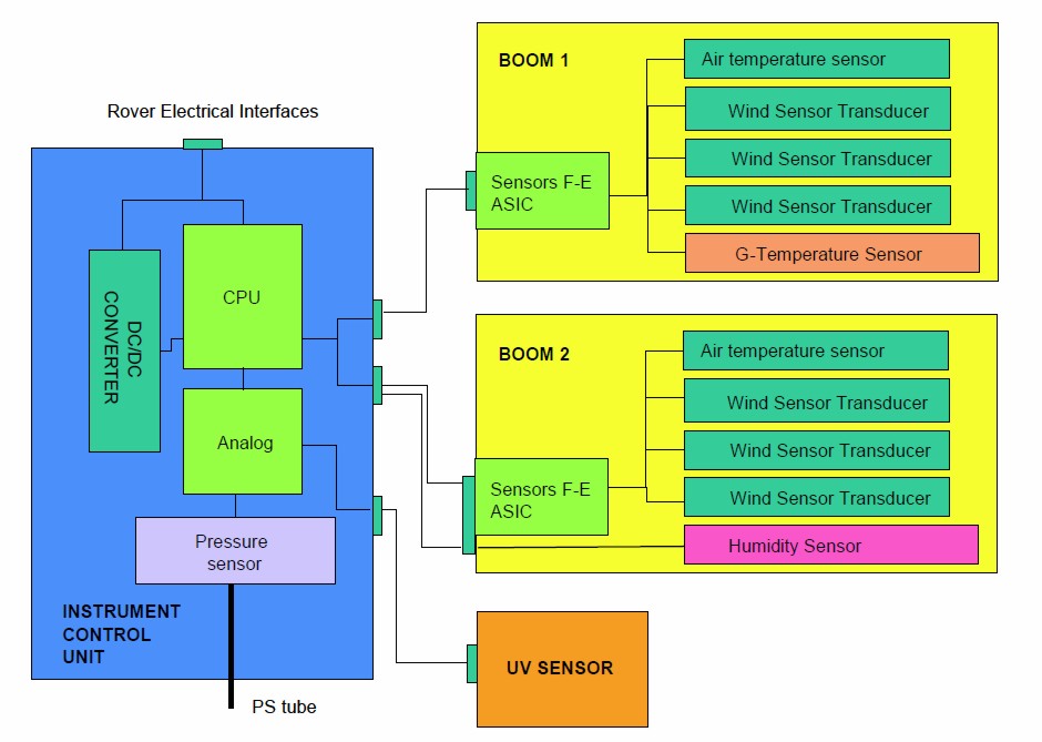
REMS block diagrma
Two of the main constraints on the REMS instrument design are the need of the booms to survive and operate in a broad range of temperatures and a mass restriction of 1.3 kg for all the instrument. Due to both conditions it was required to develop an ASIC for data conditioning which should survive in a temperature range of 140 to 340 ºK and minimize power consumption for operation.
The UV sensor is located on the rover deck and is composed of six photodiodes in the following ranges: 335-395 nm (UVA), 280-325 nm (UVB), 220-275 nm (UVC), 210-380 nm (total dose), 245-290 nm and 310-335 nm (these two bands have been selected to ease comparison with MRO data and correspond to ozone absorption bands), with an accuracy better than 5% of the full range. The sensor will be placed on the rover deck without any dust protection. To mitigate dust degradation, a magnet has been placed around each photodiode with the aim to increase as much as possible their operation time. Nevertheless, to evaluate dust deposition degradation, images of the sensor will be recorded periodically.Comparison of these images with laboratory measurements will permit the evaluation of the level of dust deposition.
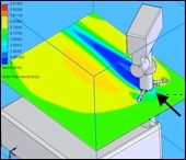
CFD simulation of the interaction between wind flow and the rover mast, different colors show wind speed perturbation and how the boom measurement will be modified
The Pressure sensor is developed by FMI and based on a Vaisala transducer. This sensor will be located inside the rover body and connected with the atmosphere by a small opening with a protection to avoid dust deposition. Its measurement range goes down to vacuum (0 to 1150 Pa) with and accuracy (end-of-life) better than 10 Pa. The relative accuracy (repeatability in the time scale of hours) is less than 2 Pa. As this component will be in contact with the atmosphere and in order to avoid any contamination of the Mars environment a HEPA filter will be placed on the opening.
Wind Sensor (WS)
The wind sensor measures the local wind speed and direction in three cylinder locations. By a combination of data recorded by the three sensors, the wind direction and speed free stream velocity is computed.
[more]
Ground Temperature Sensor (GTS)
The only way to performa a contactless measurement of a body temperature is using its infrared radiation emission. REMS GTS uses that concept: records ground infrared radiation and based on it makes an estimation of the ground temperature. [more]
Air Temperature Sensor (ATS)
A small thermistor located at the tip of a rod is the way to estimate air temperature. The rod is manufactured with a low thermal conductivity material. A second thermistor in the rod is used to estimate the heat flux from the boom body. [more]
Relative Humidity Sensor (RHS)
Changes in a film capacitance due to water molecules deposition is the concept of this sensor. It is encapsulated in a white Teflon cylinder to minimize dust deposition on the film. [more]
Ultraviolet Sensor (UVS)
The UVS is a small box, which hosts six photodiodes and its corresponding six magnets. An additional magnet, located in the middle of the box will be used to estimate the dust deposition level on the box. A thermistor bonded to one of the photodiodes is used to correct the UVS readings. [more]
Pressure Sensor (PS)
Pressure is estimated using capacitor plates that are moved by pressure. Inside the PS there are several sensor heads, which measure pressure with different levels of accuracy. [more]