UV photons have enough energy to excite and remove electrons from atoms and molecules, inducing the formation of radicals and ions. Some of these products may recombine in a chemical reaction leading to the formation of new molecules. A reliable knowledge of the UV radiation levels on the Martian surface is thus important for photochemical models of the atmosphere, for the chemistry of the surface minerals and the formation of oxidating radicals and, because of its interaction with organic molecules, is paramount for the estimate of biological doses. In particular, the most relevant organic molecules, nucleic acids (DNA and RNA) and proteins, which are furthermore common to all known living forms, are very sensitive to UV radiation. Nucleic acids show a strong absorption band in the range of 260 nm and proteins in the range of 280 nm. Therefore a high level of UV radiation can totally dissociate these molecules and sterilize a surface.
The Martian atmospheric micron-sized red dust is blown into the sky by sustained winds and convective updrafts, dust devils, dusty plumes and fully developed dust storms that can load dust at planetary scales. These processes are still poorly understood. The study of the magnitude and spectral dependence of the UV opacity will be used to quantify the dust loading and setting processes, dust size, dust scattering and absorption processes (which are required inputs for radiative transfer codes and for the interpretation of remote sensing measurements) and ozone concentration.
Instrument description:
The REMS-UV sensor measuring concept is based on the use of 6 UV photodiodes of different spectral support. UV photodiodes have the advantage of being small in size, light and robust for survival and operation under harsh conditions such as those expected for MSL. The REMS-UV sensor is placed within the rover deck, facing the sky, at a location that is visible by the rover NavCam. The whole REMS-UV unit weights only 72 g. It has 6 different Silicon Carbide (SiC) photodiodes and an RTD reference temperature sensor in an anodized aluminum and painted FR4 box of 55 mm x 68 mm x 16 mm with a D25 connector for the 7 output signals. Each photodiode weights 1 g and consists of a TO-5 housing (of 5 mm height and 5 mm diameter) with a SiC sensing surface of 1 mm^2 and a nominal field of view (FOV) of +/- 30º. The FOV is geometrically limited by the photodiode caging. When the Sun is within 30ºwith respect to the norm, the direct beam reaches the sensing dice directly or after traverse of the filter (if any). Each photodiode is embedded in a samarium cobalt magnetic ring to deflect the trajectories of in-falling dust and mitigate dust deposition. An additional magnet is placed in the center of the box below a white area. This area shall be used to re-calibrate during the mission, using camera images, the sensor obscuration (and thus sensor degradation) due to dust deposition.
The selected photodiodes have different spectral ranges: one global (named ABC) SiC photodiode with responsivity in the range 200-380 nm, and 5 filtered photodiodes named A,B,C,D and E. Each broadband photodiode shall provide a crude evaluation of the incident flux within its range of responsivity: photodiode C provides a first order estimate of the level of biologically damaging irradiance; photodiodes A and B are to be compared with terrestrial irradiances while photodiode ABC gives an estimate of the total UV irradiance, and photodiodes D and E are designed to match two UV channels of the MARCI instrument on board the Mars Reconnaissance Orbiter (MRO) satellite such that a direct comparison with simultaneous reflectance measurements is possible. Each individual photodiode provides information that can be directly compared with their equivalent measurements on Earth or on the top of the Martian atmosphere. But in addition, the combined use of the simultaneous measurements of the 6 photodiodes will provide not only better estimates of the incident irradiance per channel, but also a smooth approximation to the spectral shape of the down-welling flux.
Ultraviolet Sensor (UVS)

Color image Sensor UV on Mars (Credit: NASA-JPL)
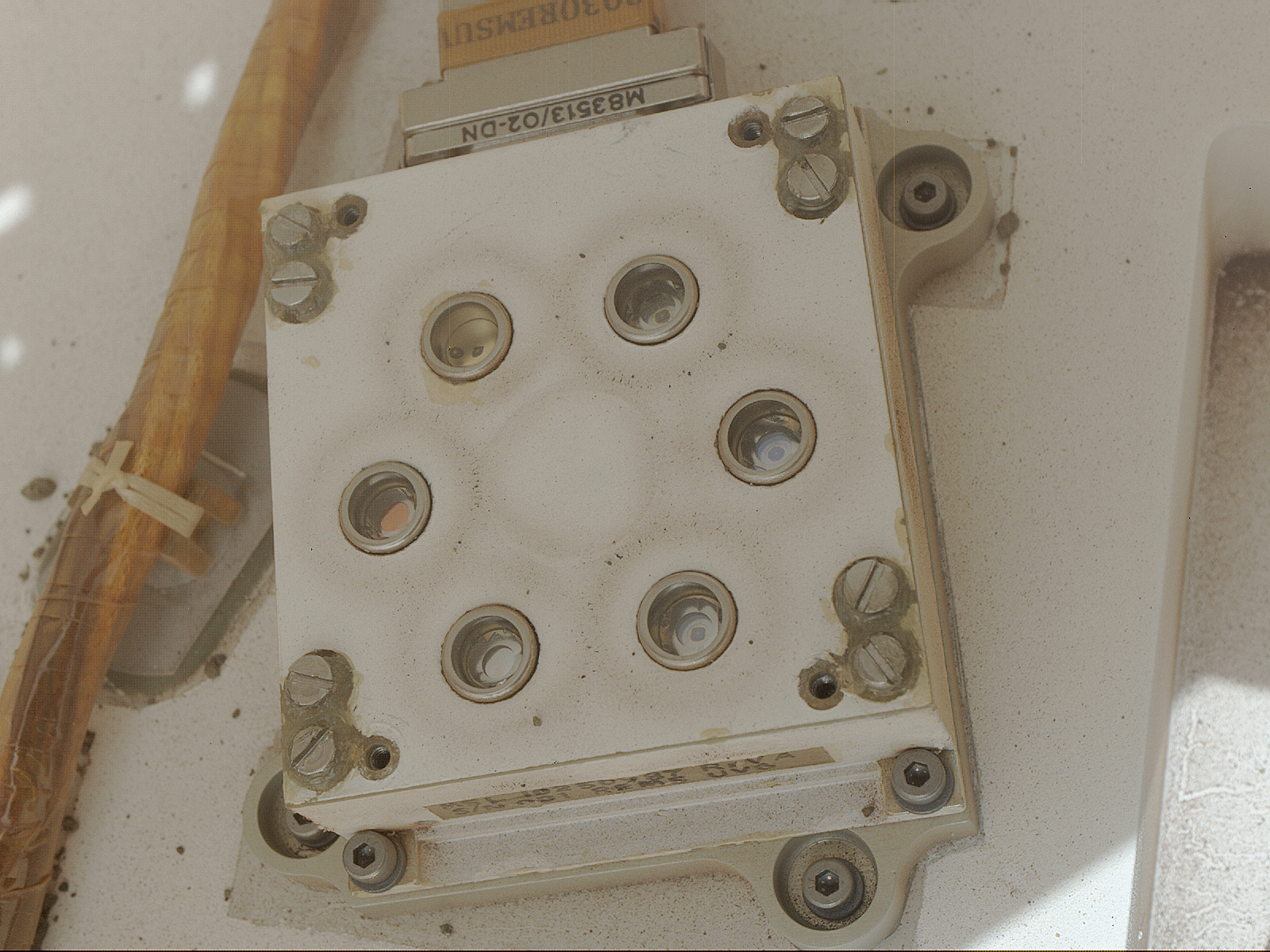
UV Sebsor over Mars surface (Credit: NASA/JPL)

UV Sensor engineering model

Inside of UV Sensor engineering model
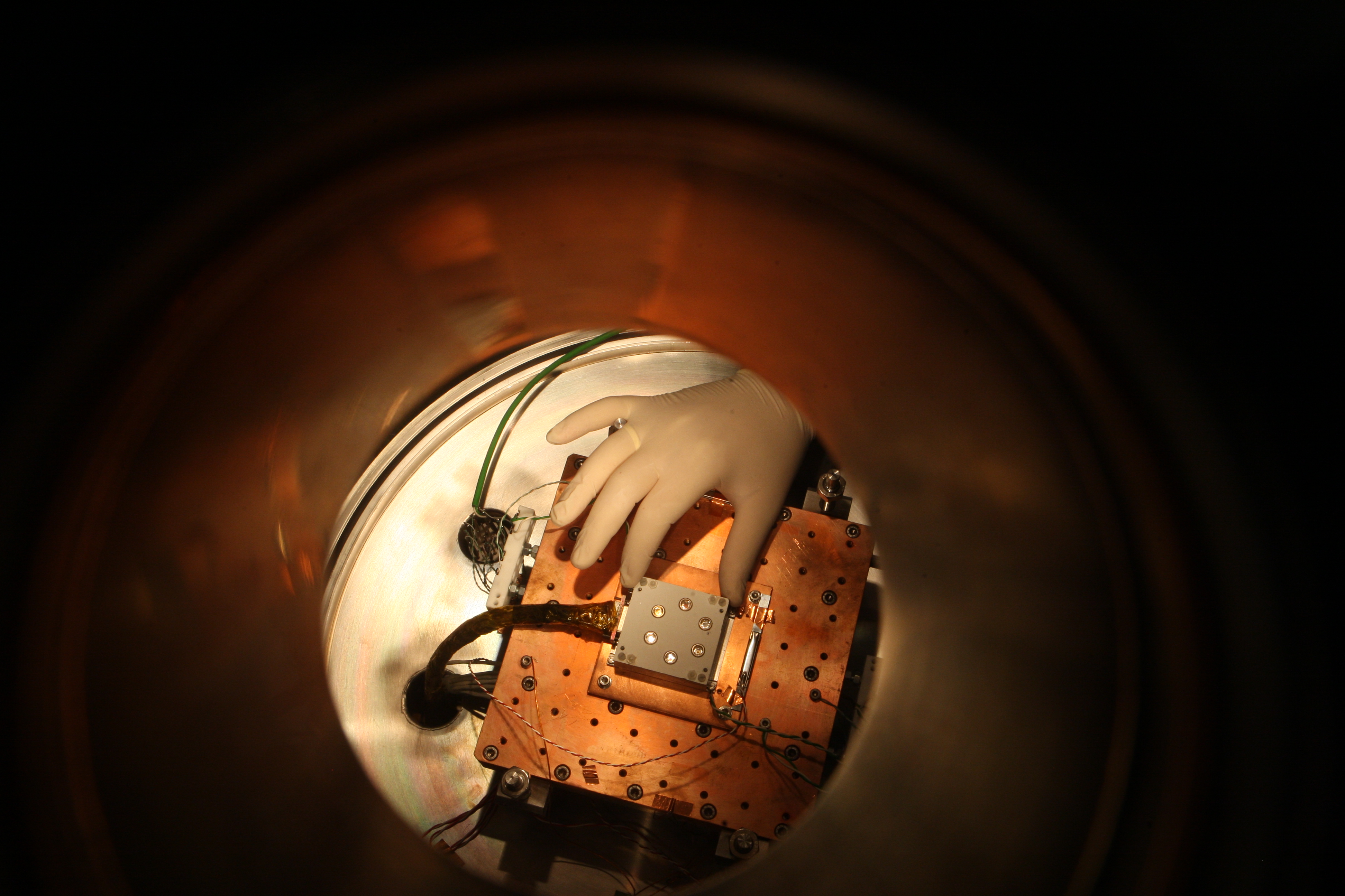
Engineering model tests of the UV Sensor inside Mars Simulation Chambers
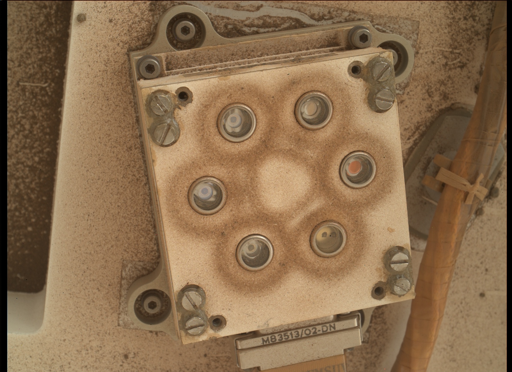
UVS Image by MAHLI. Sol 282. 2013-05-25 UTC. Image Credit: NASA/JPL-Caltech
Dust over REMS UVS