REMS wind sensor measures the wind horizontal and vertical speed as well as the wind direction. The sensor is based on hot film anemometry.
There are two REMS wind sensor units on MSL and each is mounted on separate booms or housings. These booms are designed to support the wind sensor units in order to reduce aerodynamic effects and minimize weight. REMS booms are located on the MSL rover cam-mast and placed at an angle of 120 degrees, and located at slightly different heights: 50mm difference. The different locations of the booms allows to measure wind from all directions, and in this way it can be ensured that the mast perturbation affects only one sensor unit at a time.
Wind Sensor Measuring Characteristics table:
|
Range |
Resolution |
Sampling |
|
|
Horizontal Wind Speed |
0-70 m/s |
0.5 m/s |
1 Hz |
|
Horizontal Wind Direction |
0º-360º |
30º |
1 Hz |
|
Vertical Wind Speed |
0-10 m/s |
0.5 m/s |
1 Hz |
Each wind sensor unit consists of three transducer boards with four hot dice. Each transducer board of the wind sensor unit is located 120 degrees around the boom (see figure 1) to measure local wind speed along two perpendicular directions: transversal and longitudinal. A suitable combination of all wind transducers output signals will provide the absolute wind speed value and direction.
The four hot dice in each transducer board are based on hot film anemometry. These dice, which are assembled in a square configuration, are kept at a fixed temperature difference with respect to a cold or reference die using an electro-thermal sigma-delta control loop that supplies power to the hot die. The circuit measures the power delivered to the hot die, and as the temperature difference is known, the thermal conductance from the hot die to the ambient CO2 is computed. In order to do this, additional thermal information to calculate the power lost by conduction through the supports and the wire-bonding is required, as well as thermal ambient information to evaluate radiation losses.
A full description of the four dice electronics concept can be found in (1).
The calibration tests of the wind sensor have included apart from specific tests in several wind tunnel facilities a wide range of fluid simulations to evaluate first the impact of the rover interference (both aerodynamic and thermal) in the wind measurement, calibrate the Cam-Mast influence and finally to compare and validate the wind sensor hot dice response in real tests.
(1) M.Dominguez, V. Jimenez, J.Ricart, L.Kowalski, J. Torres, S. Navarro, J.Romeral L.Castañer ‘ A hot film anemometer for the Martian atmosphere, Planetary and Space Science, 56(2008), pp. 1169-1179.
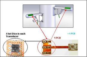
Figure 1. Wind Sensor location in REMS booms on the Rover Cam-Mast and Wind Sensor configuration
The wind sensor measures the local wind speed and direction in three cylinder spots. By a combination of data recorded by the three sensors, the wind direction and Speedy upstream is computed.
At each spot, there is an anemometer based on heat film technology. Wind Speedy is proportional to the power injected to maintain constant the Films temperature.
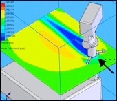
CFD simulation of the interaction between a wind flow and the rover mast, different colors show wind speed perturbation and how boom measurement could be modified.
Wind sensor working in linear wind tunnel (videos)