1. REMS GTS General Description.
The GTS measures the Martian surface kinematic temperature integrating the IR energy radiated by the ground. The GTS is located in one of the REMS booms positioned in the NASA/MSL Rover mast at 1.6m height, and it hosts the electronics employed to amplify thermopile signals. To avoid local temperature effects, the GTS focuses on a large ellipsoidal ground surface area of around 100m2, measuring its average temperature. The field of view (FOV) and its orientation was selected to avoid Rover direct vision, but the area is not far enough from the Rover to rule out its influence, specially the thermal contamination of the Radio Thermal Generator (RTG). In the following subsections a description is given of the specific characteristics of the GTS design.
Table 1.
GTS general characteristics (without electronics) and required performances
| GTS Property | Value |
| Dimensions | 40 ´ 28 ´ 19 mm |
| Mass | 20 g |
| Temperature working range (TC) (Min-Max) | 150–300 ºK |
| Ground temperature range | TC ±40 ºK |
| Resolution | 0,1 ºK |
| Accuracy | ±5 ºK |
| Field of view (FOV) | 60º(horizontal), 40º(vertical) |
1.1. Mechanical Design
The GTS mechanical structure is an ad-hoc design which tries to cope with REMS restrictions, such us the lack of a temperature stabilization control system and the impossibility of using mechanical choppers due to robustness and power consumption issues. Thus, the mechanical structure of the sensor is composed of a metal housing piece containing the IR detectors, and which further functions as thermal mass to ensure acceptably low drift in detector case temperature. Furthermore, an in-flight recalibration
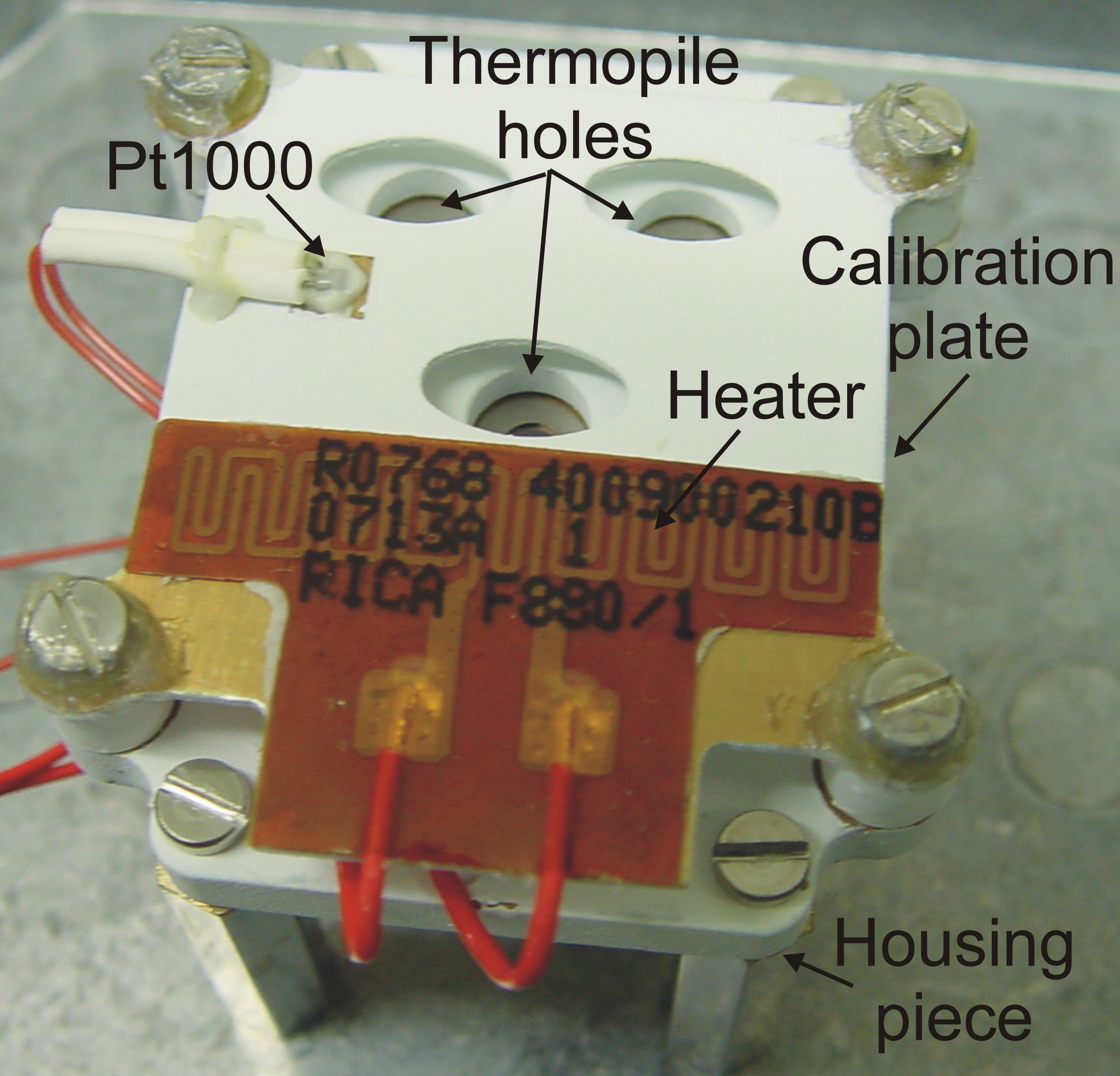
Figure 1. A photograph of the REMS GTS flight model. (Credit: Sensors 10 (2010))
system is required, due to the dusty atmosphere on Mars and the long mission duration, which may imply the deposition of dust on the detectors’ optics, leading to deterioration in their output signals. This system is implemented by a simple low mass and high emissivity calibration plate (Figure 1), which can be heated to a given temperature and is placed in front of the thermopile housing piece, so that each IR detector looks at the ground through a hole in the plate. Thus, part of the FOV is obstructed by the calibration system, limiting the measurement solid angle (Table 1).
The calibration plate is electrically heated using an electrical heater consisting on an etched-foil resistive heating element laminated between layers of polyimide, a flexible and thin insulator. And its temperature is measured using a specific Resistor Temperature Detector (RTD), a Pt1000, attached to its surface. This recalibration system with no moving parts avoids complicated and costly commercial air purge systems to maintain the sensor window free of dust.
1.2. Infrared Detectors
The GTS IR detectors are thermopiles, since they are capable of functioning at almost any operational temperature, and they are small and lightweight. In addition, they are sensitive to all the IR spectra, comparatively cheap and require simple readout electronics, enabling further reductions to be made in the weight and size of the complete instrument. Finally, thermopiles can operate without the need for any sort of temperature control system, because they are less sensitive than other systems to the emergence of thermal gradients.
However, thermopiles are not standard parts for space applications and at present no formally space-qualified thermopile sensors exist. Nevertheless, it should be noted here that the Infrared Thermal Mapper (IRTM) experiment on the VIKING mission and the MUPUS-TP experiment on the ROSETTA mission have proven the suitability of this kind of detector for measuring low object temperatures under space conditions. The thermopile model selected for the REMS is the TS-100, from the Institute for Physical High Technology (IPHT) in Jena (Germany), encapsulated within a TO-5 with no optical system but rather a thermopile filter built to specifications and pre-bonded onto the TO-5 as the thermopile window. The thermopiles have a non corrosive insulator and transparent atmosphere filling, as well as an internal RTD, a Pt1000, to measure temperature at the thermopile case base, which acts as a temperature reference for the thermocouple cold-junction.
Table 2. GTS thermopiles characteristics
| GTS Item | Wavelength Sensitivity |
Unit | Range Min-Max |
Sensitivity Min-Max |
| Thermopile A
(Group of thermocouples) |
8-14mm
(average transmittance 75%) |
Volts | ±1,6mV | 35-70mV/ºK |
| Thermopile B
(Group of thermocouples) |
15,5-19mm
(average transmittance 65%) |
Volts | ±0,64mV | 12-16mV/ºK |
| Thermopile C
(Group of thermocouples) |
14,5-5,5mm
(average transmittance 65%) |
Volts | ±0,25mV | 4,7-6,6mV/ºK |
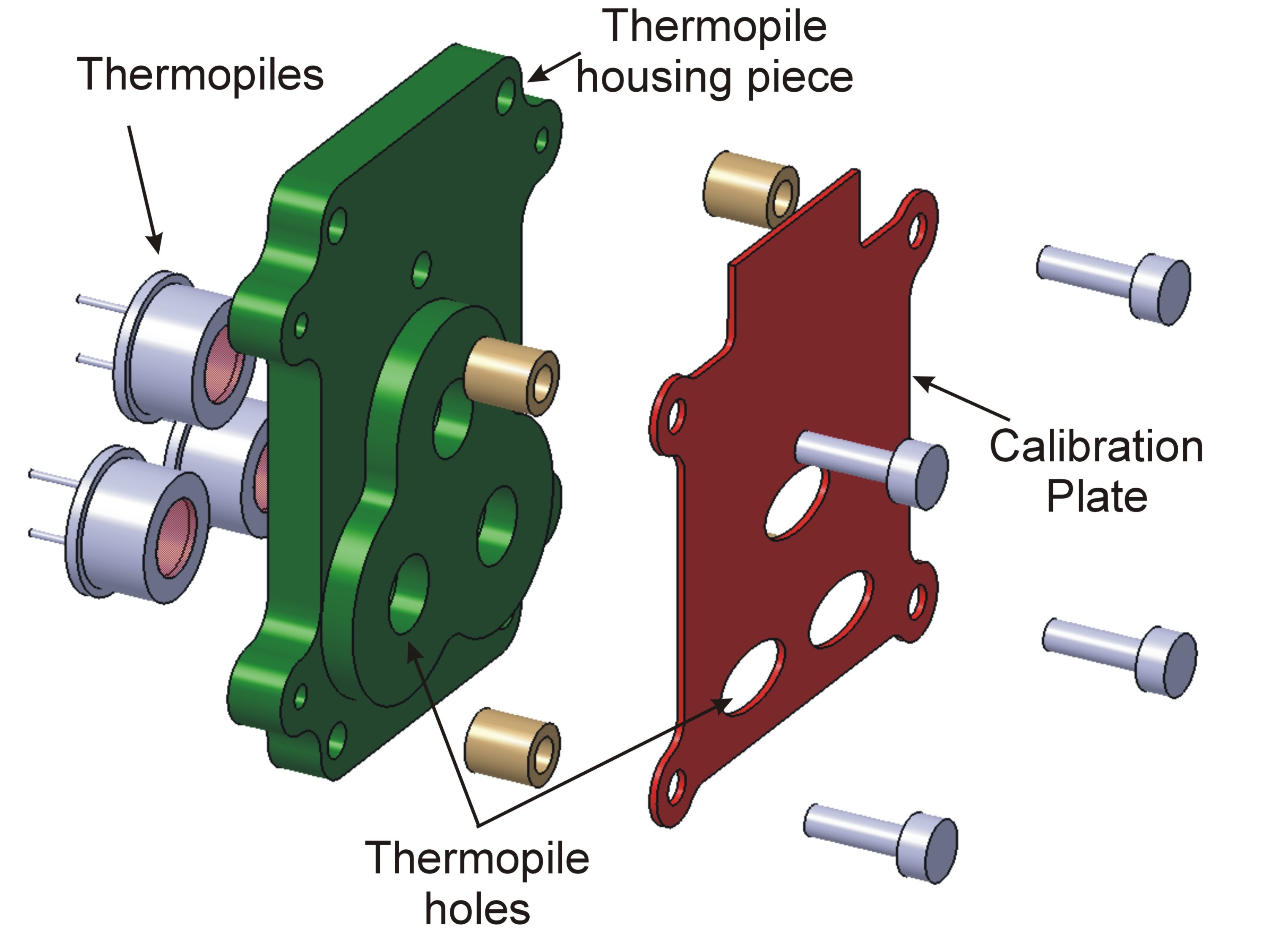
Figure 2. The 3D mechanical layout of REMS GTS (Credit: Sensors 10 (2010))
.
The GTS uses three different thermopiles on three different infrared wavelength channels, A, B and C (Table 2). The first two bands are optimized for the upper and lower Martian ground temperature ranges. Following Wien’s law, the maximum blackbody spectral radiance for a given temperature is given by µmax[µm]=2898/T[ºK]. If the maximal and minimal Martian temperatures are 300ºK and 150ºK, then the sensor is designed to work optimally in the range from 9.9µm to 19.3µm. Additionally, the measurements must be performed within a range where the ratio of IR radiance emitted by the Martian surface to the solar IR radiance reflected by the Martian surface, for typical Martian soil emissivities, is significantly greater than one. This condition is achieved above 8 m, where the solar reflected radiance is smaller than 0.5% for the lower ground temperature. Finally, the last restriction for the selection of these bands is avoidance of the CO2 atmospheric absorption band centered at 15µm and bandwidth of 1µm, the main component of the Martian atmosphere. The third band is centered on the CO2 absorption band. This allows any residual influence that the atmosphere may have on the other two thermopile bands to be determined.
1.3. Electrical Design.
The GTS electrical output signals (thermopile output voltage and the resistance of the different Pt1000s, those inside the thermopiles and the one on the calibration plate) are sampled by REMS electronics. This electronic system presents a distributed architecture (Figure 3). The Instrument Control Unit (ICU) is located inside the MSL Rover body, whereas the data acquisition electronics are located inside REMS booms. This architecture permits optimization of the total harness, and at the same time reduces coupled noise in analog signals. REMS data acquisition uses a mixed signal (Digital-Analog) Application Specific Integrated Circuit (ASIC) to implement the REMS sensor and driver front-end interface, due to space and weight restrictions.
Figure 3. REMS GTS electronics architecture:
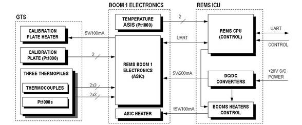
Table 3 summarizes the GTS data production and power budget, considering only the energy directly consumed by the GTS sensors and heater.
Table 3. GTS data production and power budget
| Operational Mode | Bit/Sec | Kbits/Sol | Power (mW) | Power/Sol (mWh) |
| Nominal
(1sps during 5 min every hour) |
112 | 806.4 | 0.25 | 0.5 |
| Flight Calibration (1sps during 15 min every week) |
112 | 14.4 | 500 | 17.8 |
| Total | 820.8 | 18.32 |
* ASIC power consumption and ASIC energy necessary to reach operational temperature is not considered.
Ground Temperature Sensor (GTS)
Mars average surface temperature is 220 K and varies widely over the course of a Martian day, from 145K during the polar night to 300 K on the equator at midday at the closest point in its orbit around the Sun, with diurnal variations of up to 80–100K.
Mars undergoes very extreme gradients between the ground and the atmosphere at 1.5 m above the surface, with differences of ±40K.
Typical emissivity values of Martian soils from 6 to 25μm vary between 0.9 and 1.
GTS measurements are conditioned by different factors:
1. Ground emissivity different form 1 and uncertainty in its real value, resulting in different kinematic and brightness temperatures.
2. Martian atmospheric absorption, which has a strongly absorbing band cantered at 15 µm due to the CO2.
3. A dusty atmosphere absorbs and emits IR energy inside the measurement band, disturbing the energy coming from the ground, and deteriorates pyrometer optical performance.
4. The thermal environment in which the GTS is working (rover and instruments thermal properties and behaviours) introduces uncertainty output measurements.