The REMS Air Temperature Sensor (ATS) consists of a set of Minisens RTD thermistors type PT1000 Class A of 1.2mm x 1.6mm. They are bonded at the free end of a multi layer FR4 rod with 2×3 mm2 section and 35mm long, with its cables soldered to the dedicated pads. In the other end of the PCB board similar pads electrically link the traces with the pads of the ASIC PCB, using a pair of cables.
On the surface of a FR4 layer located inside the beam are printed the PCB traces required to transmit the electric signals from the sensor to the ASIC electronics. The PCB traces are 17µm thick and 0.25mm wide and are printed in a zig-zag shape which tries to maximize the total length in order to increase heat losses by conduction and minimize the heat conduction from the ASIC and boom to the RTDs.
The ATS consists not only of the Pt1000 sensor on the tip, but of the FR4 as a whole and the two Pt1000 sensors that monitor its temperature profile. This information, together with a knowledge of the temperature at the base of the FR4 (boom temperature), shall be used to estimate the temperature of the fluid around it. Having these three temperatures, one can estimate simultaneously the temperature decay profile (which depends on the instantaneous convection-conduction scenario) and the fluid temperature univocaly with independence of the thermal contamination from the boom.
An ATS is mounted on each boom, at approximately 1.6 m above the Martian surface and below the ASIC housing in the lower part of the Boom structure with a 60 º orientation with respect to the boom longer axia (pointing towards the bottom-front direction).
Air Temperature Sensor (ATS)

Air Temperature Sensor
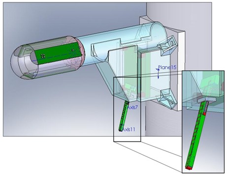
3D Model of Air Temperature Sensor